URL Slug: industrial-membrane-switch-emi-shielding
Meta Description: Learn how EMI shielding membrane switch design protects industrial HMIs from interference. Explore shielding layers, grounding strategies, and tail protection methods.
Walk into any modern factory and you will immediately notice how electrically “busy” the environment is. Servo drives accelerate motors, switching power supplies operate continuously, and inverter cabinets generate broadband electromagnetic noise.
In this setting, the Human-Machine Interface (HMI) mounted on equipment panels must remain stable and predictable. Yet many engineers have encountered situations where a control panel behaves strangely — phantom key presses, delayed responses, or occasional communication glitches.
In a large percentage of these cases, the root cause is insufficient EMI shielding membrane switch design.
Based on our project experience at Xinbixi Electronic Technology Co., Ltd., this is not a rare edge case but a recurring engineering consideration whenever membrane switches are installed near high-power industrial electronics.
Why EMI Matters for Industrial Membrane Switch Interfaces
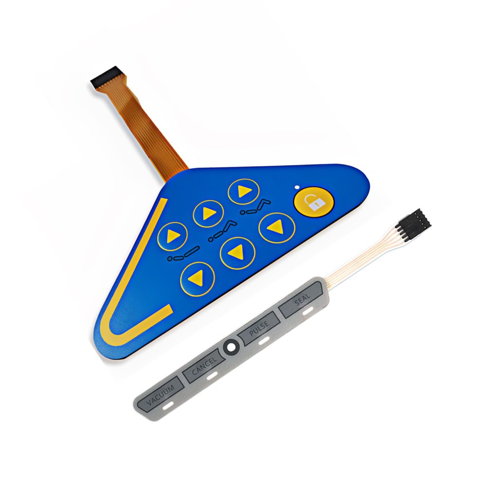
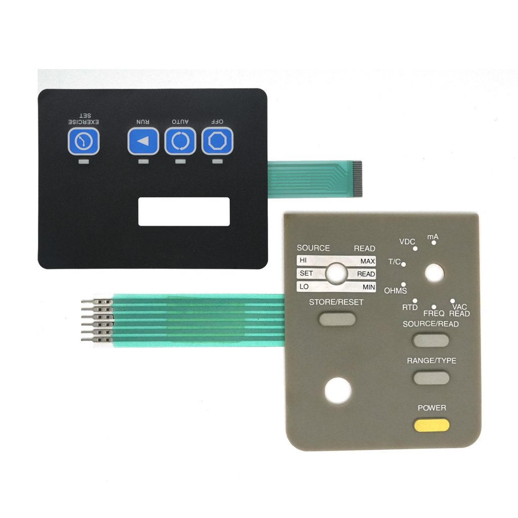
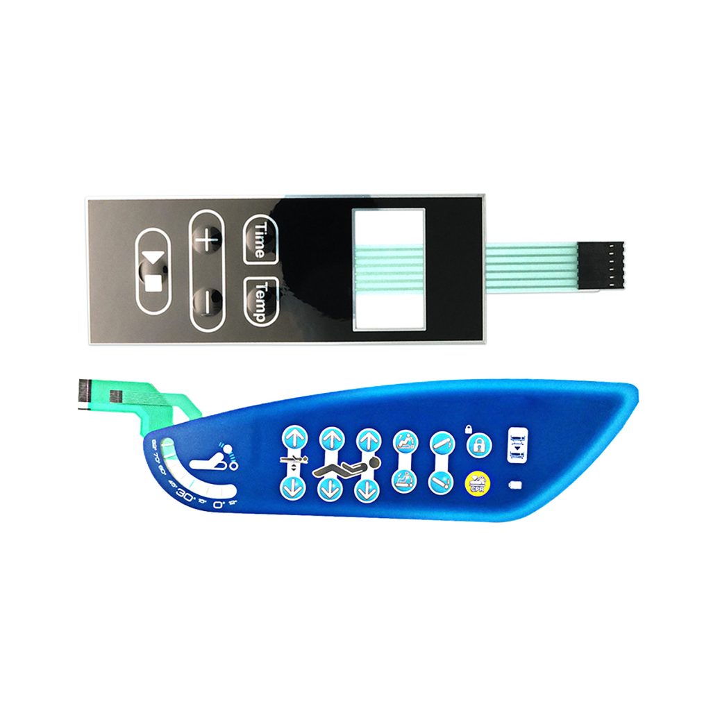
A membrane switch assembly is fundamentally a layered structure composed of polymer films, printed circuits, adhesive layers, and flexible tails. While optimized for sealing and durability, this thin multilayer stack can unintentionally behave like an antenna.
Without proper industrial HMI EMI design, several issues may appear:
- False triggering caused by induced signals
- Signal instability between the switch and controller
- Communication errors in PLC-connected panels
- Display or LED anomalies in integrated panels
These problems often occur intermittently, making troubleshooting difficult and increasing maintenance costs.
As automation density continues to increase, membrane switch EMI protection is gradually shifting from “optional enhancement” to baseline design requirement.
Typical Sources of Industrial Electromagnetic Interference
Before defining a shielding strategy, engineers must understand the dominant interference sources surrounding the interface:
- Switching power supplies within control cabinets
- Variable Frequency Drives (VFDs) generating high-frequency switching noise
- Servo drives producing broadband emissions during acceleration cycles
- Parallel routing of high-voltage motor cables
- Poor grounding architecture inside machine frames
When a membrane interface is mounted directly on equipment panels containing these sources, the probability of interference coupling increases significantly.
Shielding Layer Integration Inside the Membrane Stack
The core of any EMI layer membrane switch is the conductive barrier embedded within the structure. Its role is to intercept and redirect electromagnetic energy before it reaches sensitive signal traces.
In practical projects, several shielding approaches are commonly used:
Printed Silver Mesh
A cross-hatched conductive pattern screen-printed onto a film layer provides balanced performance and cost efficiency. This method is widely applied in general industrial automation panels where moderate shielding effectiveness is sufficient.
Laminated Copper or Aluminum Foil
For high-noise environments such as inverter cabinets or heavy motor control systems, foil layers offer superior conductivity and higher shielding effectiveness. They are often combined with insulation gaskets or structural backing layers.
Conductive Paste Layers
A continuous conductive coating can simultaneously enhance EMI suppression and provide basic ESD mitigation, making it suitable for compact interface designs.
Transparent Conductive Shielding
When panels include display windows, transparent shielding solutions such as fine conductive mesh or ITO coatings allow visibility while maintaining electromagnetic protection.
The choice of method depends on noise spectrum, required shielding effectiveness, cost constraints, and mechanical integration.
Grounding Strategy: Where Shielding Becomes Effective
A shielding layer alone cannot function without a proper discharge path. One of the most common design oversights in shielded membrane switch panels is incomplete grounding implementation.
Effective membrane switch grounding design typically follows several principles:
- Maintain a low-impedance ground path through wide conductors
- Use single-point chassis grounding to avoid loop currents
- Separate shielding ground from sensitive digital signal return paths
- Ensure reliable mechanical contact at connector interfaces
When grounding is implemented correctly, the shielding layer transitions from passive barrier to active interference sink.
Tail Shielding: The Frequently Overlooked Weak Point
Even well-designed panels can experience EMI issues through the flexible tail connection. The tail behaves as an extended conductor capable of picking up radiated noise along its routing path.
Practical tail shielding strategies include:
- Dedicated ground traces running parallel to signal lines
- Optional laminated shielding layers forming a shielded FFC structure
- External ferrite suppression components when cable length increases
- Controlled routing distance from motor or power harnesses
In several industrial projects, improvements in tail shielding alone resolved persistent interference symptoms without modifying the panel structure.
When EMI Shielding Becomes Mandatory
While some low-power equipment can operate without dedicated shielding, certain applications consistently benefit from a shielded membrane switch architecture:
- Automation systems integrating servo or inverter control
- Medical devices requiring stable signal integrity
- Heavy industrial equipment exposed to high current switching
- Outdoor or mining equipment with extended cable runs
- Systems pursuing CE or FCC electromagnetic compliance
In these environments, EMI design decisions made during early development stages can significantly reduce later validation effort.
Practical Engineering Perspective
From an engineering standpoint, EMI shielding should not be viewed as a discrete feature but as part of holistic interface reliability design. Material selection, stack configuration, grounding topology, and cable routing all interact to determine final electromagnetic behavior.
In real projects, the most robust solutions often emerge from collaborative evaluation between equipment engineers and interface manufacturers, particularly during prototype validation phases.
Conclusion
Industrial membrane switches operate in environments far more electrically complex than their appearance suggests. As automation equipment grows in power density and functional integration, electromagnetic compatibility becomes a defining factor in interface reliability.
A thoughtfully implemented EMI shielding membrane switch architecture — combining conductive layers, disciplined grounding, and protected tail routing — enables HMIs to remain stable even in electrically aggressive surroundings.
For engineers designing next-generation industrial equipment, incorporating EMI considerations early is not merely preventative design but a direct investment in operational continuity.