
A customer sent us a 2,000-piece production order after their sample was approved without a single revision comment. Three weeks later, the batch arrived at their assembly plant and stopped the line. Print registration had drifted on roughly 30% of the panels. Emboss height was inconsistent between keys at the panel center and keys near the edges. Adhesive had squeezed out along two cutout edges, leaving visible beads under the display window frame.
None of it showed up in the sample.
We see this pattern regularly when taking on transfer orders or supporting a customer’s first volume run. The sample passed because it was built by hand, slowly, with individual corrections at every step. The production run exposed what the design actually required from a machine running at volume.
Sampling Conditions vs. Production Conditions
When a sample is made in-house, the press technician positions each sheet manually, checks layer registration by eye before every pass, and pulls any piece that looks marginal. Adhesive lamination is done by hand at slow speed. The embossing press runs a single cycle on a fully stabilized tool. The die cut is made on a fresh setup.
Production volume changes every one of those conditions. Registration is held by mechanical stops, not individual adjustment. The lamination machine runs at a fixed feed rate and nip pressure from the first sheet to the last. The embossing press cycles continuously, and tool temperature drifts as the run progresses. The die runs until its next scheduled maintenance interval.
A design that was built around the sample conditions — without accounting for how the machines behave at speed — will produce a batch that doesn’t match the sample. This is the actual root cause behind most first-run rejections we review.
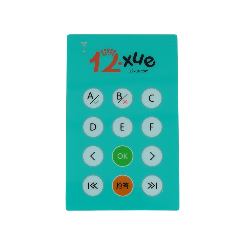
Registration Drift in Multi-Layer Screen Printing
Back-printed overlays typically require two or more ink passes: a white opacity base layer, then the color graphic layer on top. On a sample, each pass is registered manually. On a production run, registration is held by pin guides or press-bed stops.
These mechanical references are accurate but not perfectly stable across hundreds of sheets. On a 500-sheet run at production speed, cumulative drift between the first and last sheet can reach 0.3mm to 0.5mm. On a solid-color panel this is undetectable. On a design where a transparent display window is bordered by a printed color frame, a 0.4mm drift produces a visible shadow on one edge — the color layer from the first pass showing through the window boundary.
From a manufacturing perspective, the answer is not tighter press calibration on every job. The answer is a minimum clearance buffer built into the design: the printed frame should stop at least 0.8mm from any transparent zone boundary. That buffer absorbs normal press variation across the full run. A design without it will show registration issues at volume even on a well-maintained press.
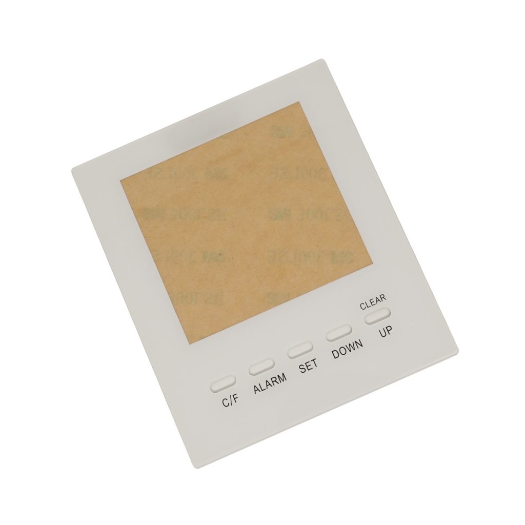
Tolerance Stack-Up Across Assembly Layers
A membrane switch assembly stacks three or more layers — graphic overlay, spacer, circuit layer — each of which carries its own dimensional tolerance off the die. In sampling, layers are trimmed to fit individually, so the assembly aligns cleanly regardless of individual piece variation.
In production, each layer ships at its own tolerance. The overlay outer contour holds ±0.2mm. The dome layer holds ±0.2mm. The spacer holds ±0.2mm. When all three layers hit their maximum allowable deviation in the same direction, cumulative misalignment reaches 0.6mm. A display window that was centered in the sample sits visibly off-center on the finished assembly.
This only shows up at volume, because hand-assembled samples correct each layer against the previous one. We calculate worst-case stack-up during DFM review before sampling, either by tightening individual layer tolerances on critical dimensions or by specifying additional clearance on window apertures to cover the worst-case condition. Doing this after the first production batch fails is considerably more expensive.
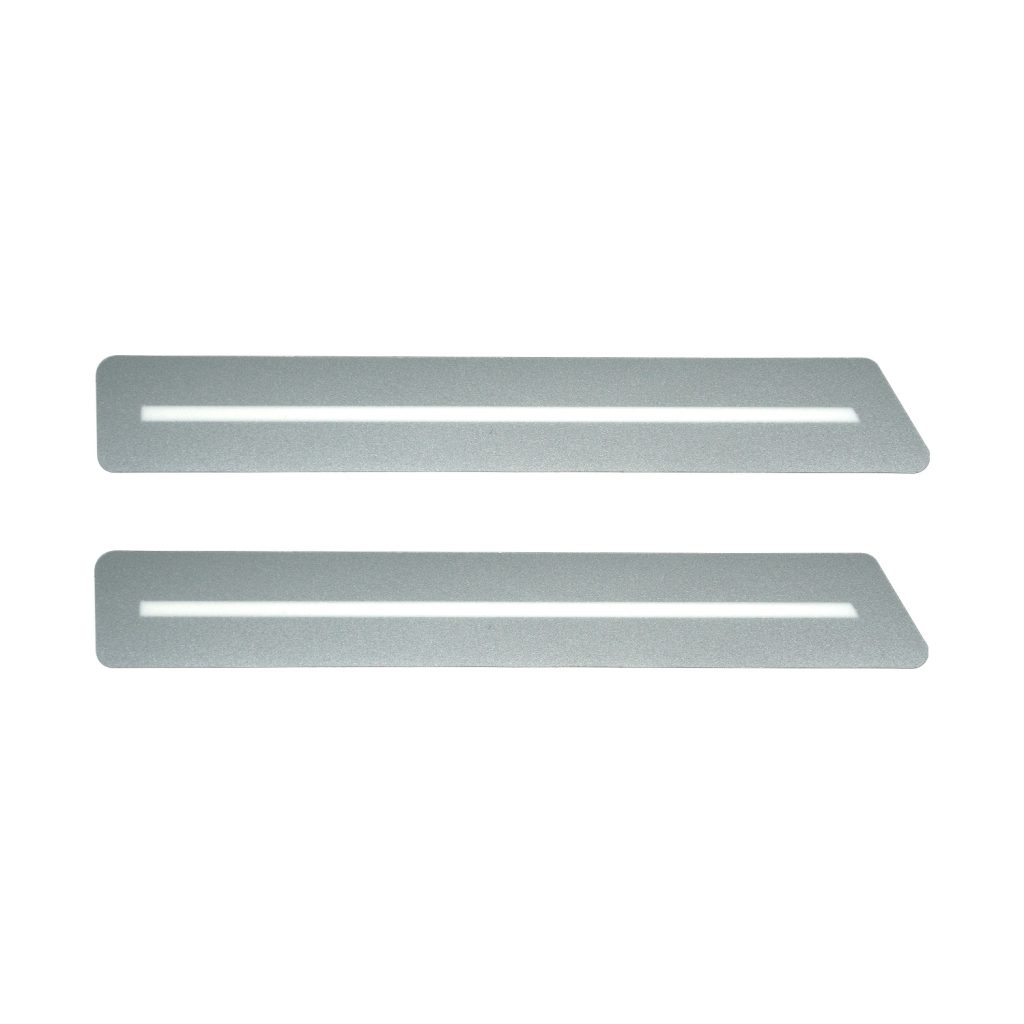
Emboss Height Variation Across Multi-Cavity Tools
Heat-forming polycarbonate into embossed key profiles requires consistent temperature distribution across the full tool face. A single-piece sample is formed on a fully pre-heated, stabilized tool running one cycle. Temperature is uniform.
A production press runs continuously. On a multi-cavity tool, the edge cavities are exposed to ambient air along the tool perimeter and run several degrees cooler than the center cavities. The temperature differential is small — sometimes 5°C to 8°C — but it produces measurable variation in emboss height. Center keys may form 0.1mm to 0.15mm deeper than corner keys over the course of a shift.
On a panel with keys clustered in a single central zone, this doesn’t matter. On an industrial control panel with keys distributed across the full panel width, the variation is detectable by hand and visible under raking light on a flat surface. Customers who specified tight emboss height tolerances for tactile uniformity find that production panels don’t feel the same as the sample.
The fix is a temperature compensation profile run during press setup, adjusting edge cavity parameters to match center cavity output. This is done as part of our press trial before production release. It has to be looked for deliberately — it won’t show up in a standard first-article inspection unless emboss height is being measured at multiple positions across the panel.
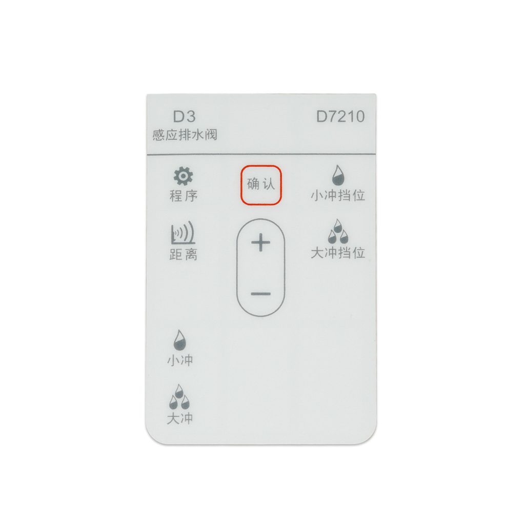
Adhesive Squeeze-Out at Internal Cutouts
Hand-laminated samples are made slowly: the adhesive liner is peeled back and the film is lowered onto the substrate by hand, then pressed with a roller. Adhesive displacement at cutout edges is minimal because the application speed is low.
Machine lamination applies the adhesive at constant feed speed under nip roller pressure. At internal cutout corners — display window openings, connector slots — the adhesive at the cut edge has nowhere to go under compression and squeezes outward slightly. On a design where the adhesive layer extends fully to the cutout edge and the corner is a sharp 90-degree angle, this produces a visible adhesive bead along the cutout perimeter.
The standard correction is an adhesive step: the adhesive layer is trimmed 0.5mm to 1mm back from internal cutout edges during die cutting. This step is not always included on hand-laminated samples because it isn’t needed at slow application speed. When a sample is approved without it and production runs with machine lamination, the cutout edges on the production batch look different from the sample. Specifying the adhesive step before sampling ensures the sample represents what the machine will actually produce.
Closing the Gap Between Sample and Production
The four issues above share a common characteristic: they are not defects caused by poor workmanship on the production floor. They are design conditions that work fine at one piece and produce consistent failures at volume. The production run didn’t fail — the design was never validated against production conditions.
In long-term OEM projects, the customers who avoid first-run rejections are the ones who bring the factory into the design review before the sample is made, not after it passes. A DFM review at that stage is a brief technical conversation about clearances, tolerances, and process parameters. It costs nothing and changes the outcome significantly.
At BX-PANEL, every new part goes through DFM review before sampling. Window clearances are checked against press registration tolerance. Tolerance stack-up is calculated for all multi-layer assemblies. Adhesive step dimensions are specified for every internal cutout. Emboss geometry is flagged for temperature profiling if the key layout spans a large tool area. The sample is built to the same process parameters the production run will use.
Our Xiamen facility has been running this workflow for over 10 years, with hundreds of workers across dedicated pre-press, printing, embossing, lamination, and assembly departments. When a production order releases, the process parameters are already documented from the sampling stage — not rebuilt from scratch.
Contact BX-PANEL
Xiamen XINBIXI Electronic Technology Co., Ltd. (brand: BX-PANEL) manufactures custom graphic overlays, membrane switches, and integrated control panel assemblies for industrial, medical, and commercial equipment.
- Email: [email protected]
- Website: www.bx-panel.com
- Capabilities: Custom graphic overlay manufacturing, membrane switch production, embossed panel assembly, DFM review, die-cut prototyping