When the first prototype of a custom Human-Machine Interface (HMI) arrives, the moment of truth happens when the power is turned on. If the LED backlighting reveals glaring hotspots, shadowed corners, or light bleeding from the edges, a premium piece of medical or industrial equipment suddenly feels cheap and unreliable.
Many OEM engineers assume the fix is simply adding more LEDs or cranking up the brightness. But in the reality of manufacturing, backlit membrane switch design is rarely an electrical issue—it is an optical and mechanical challenge.
If you are dealing with uneven illumination, the root cause lies in the synergy between optical structure design, material compatibility, and the physical stack-up. Here is a factory-floor breakdown of how to engineer industrial-grade, perfectly uniform light windows.

1. The Graphic Overlay: It is a Filter, Not Just a Window
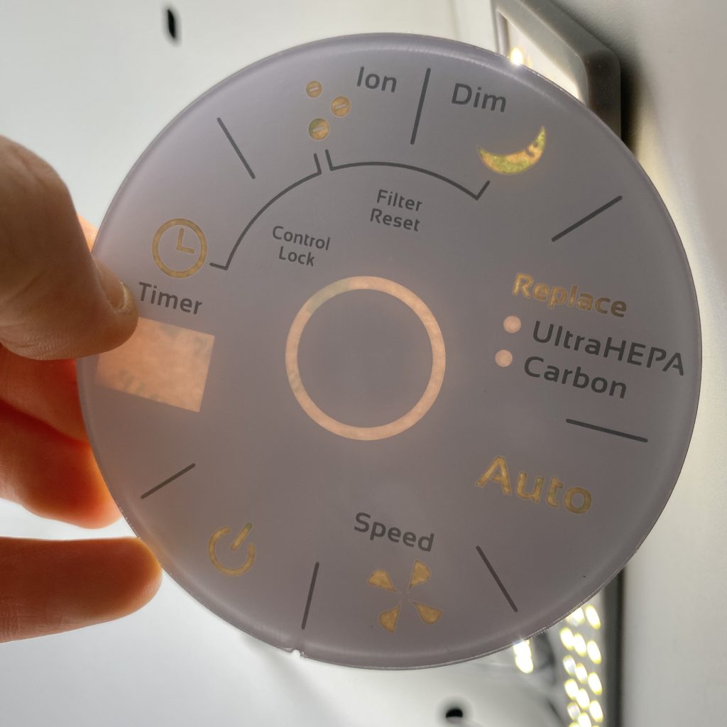
The first barrier to uniform backlighting is the transparent area on the front panel. Many designers focus only on the dimensions of the graphic overlay light window, neglecting the critical role of ink density and screen-printing precision.
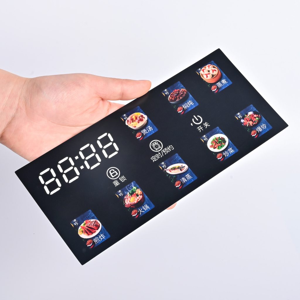
- Mastering the Dead Front Design: To achieve a true “hidden until lit” effect (dead fronting), the ratio of the background blackout ink to the translucent window ink must be meticulously controlled. A mere 5% deviation in ink thickness or halftone dot gain during printing can result in massive batch-to-batch brightness variations.
- Edge Transitions: The boundary where the transparent window meets the opaque background is a high-risk zone. A harsh, vertical ink edge can cause total internal reflection, creating an unsightly “halo” effect around the icon. Experienced manufacturers use a gradient dot transition or stepped overprinting to soften this edge.
2. Taming the Point Light Source (Diffusion Strategy)
Surface-mounted LEDs are inherently point light sources. Converting a harsh, concentrated beam into a soft, uniform area light requires a dedicated diffusion strategy within the membrane switch materials stack-up.
- Optical Diffusion Layers: Inserting a specialized PET diffusion film with specific haze levels between the LED and the overlay scatters the concentrated beam, effectively eliminating the central hotspot.
- Translucent White Back-Printing: By printing a semi-transparent white ink layer heavily loaded with titanium dioxide particles on the underside of the overlay, the light undergoes diffuse reflection, filling in the dark corners of the window naturally.
3. Edge-Lit vs. Direct Backlighting
A common engineering misconception is that “more LEDs equal better uniformity.” In reality, packing too many LEDs into a circuit increases power consumption, generates excess heat, and creates overlapping light cones that cause dark interference fringes.
Unless your Z-axis space is completely unrestricted, pointing an LED directly up at the viewing window is asking for hotspots. An edge-lit LED backlighting membrane switch solution is strongly recommended. This utilizes a Light Guide Film (LGF) or fiber optics to distribute light horizontally across the panel, extracting it uniformly from the bottom surface upward. It requires fewer LEDs and delivers a vastly superior, homogenous glow.
4. Building the “Blackout Wall” to Prevent Light Leakage
A perfectly uniform window is instantly ruined if light escapes from the edges of the keys, mounting holes, or the gap between the panel and the enclosure. Preventing light leakage in a membrane switch requires a strict physical barrier.
- The Blockout Ink Layer: A dense layer of opaque dielectric or specialized black/silver blockout ink must be screen-printed on the non-transmissive areas of the circuit layer. This stops light from traveling laterally through the clear PET substrate.
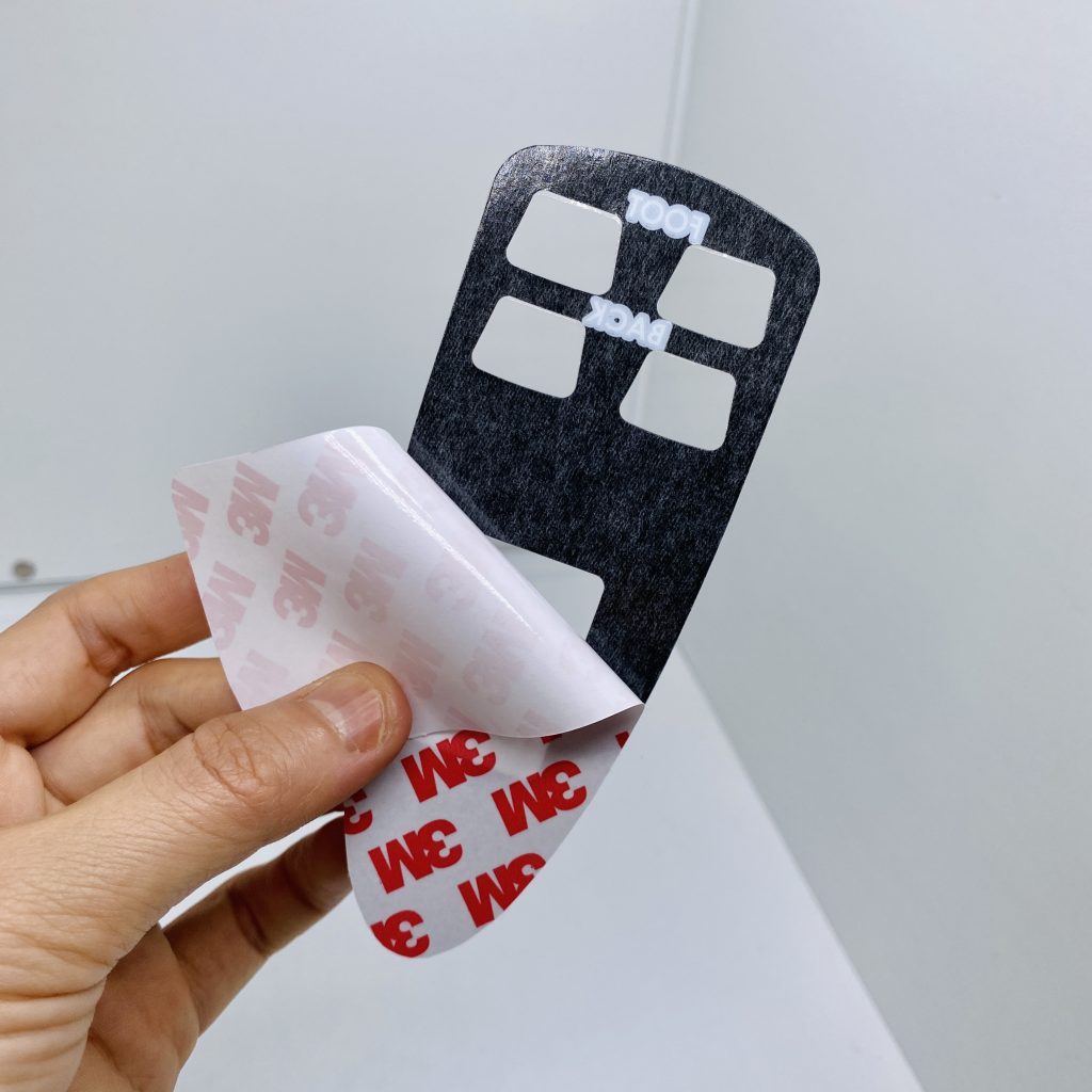
- Adhesive Routing: The pressure-sensitive spacer adhesive (like 3M) is not just for bonding—it is an optical seal. Designing a closed-loop adhesive frame tightly around the light window absorbs stray light and kills edge glow before it starts.
Common Prototyping Mistakes to Avoid
Based on our review of hundreds of OEM design files, these three errors most frequently lead to prototype failures:
- Squeezing the Z-Axis: If the mechanical stack-up height is too tight, the diffuser film is pushed directly against the LED. Without a sufficient physical “mixing distance” for the light to spread, you will see a sharp reflection of the LED die right through the window.
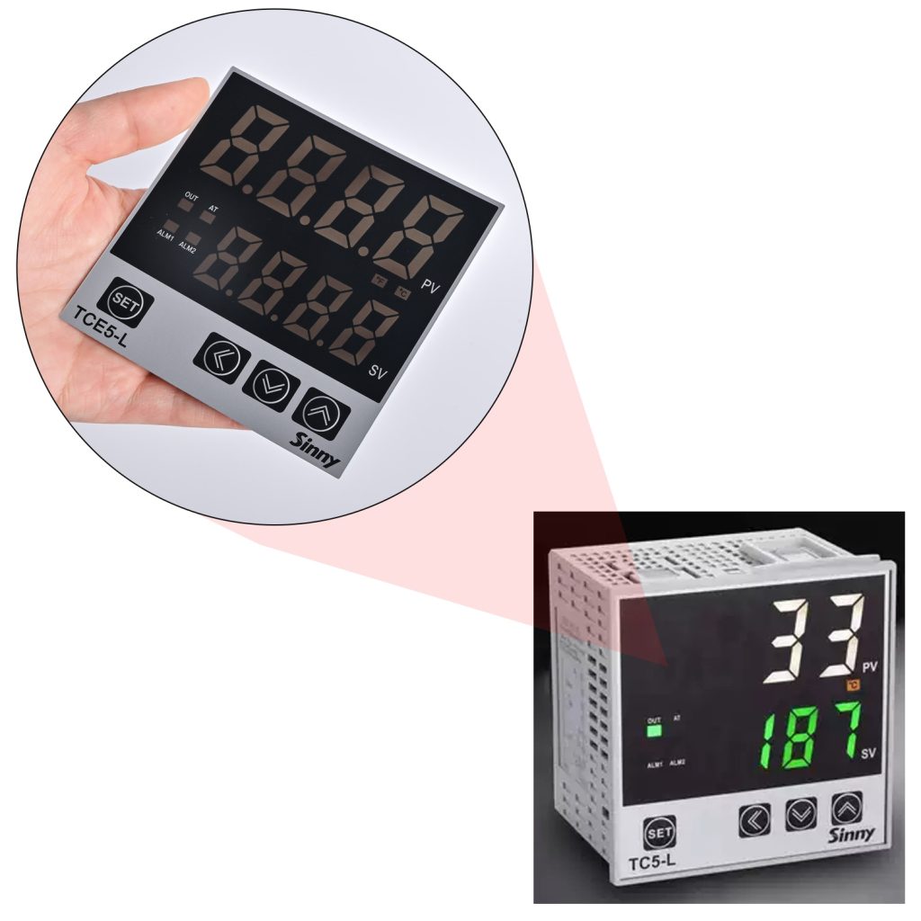
- Chromatic Interference (Color Shifting): Using a cool white (bluish) LED combined with a standard plastic substrate that has a natural yellowish tint will result in a final output color that appears distinctly greenish, failing your brand’s color matching specs.
- Late-Stage Discovery: Finding out your backlight is uneven during the Engineering Validation Test (EVT) stage means you now face costly PCB layout changes and tooling modifications. Optical considerations must be locked in during the initial blueprint phase.
How BX-PANEL Engineers Reliable Illumination
Solving uneven backlighting requires managing the complex intersection of optics, materials, and circuitry.
With over a decade of OEM support experience and massive in-house manufacturing capabilities, Xiamen XINBIXI Electronic Technology Co., Ltd. (BX-PANEL) provides end-to-end optimization for demanding HMI projects. We don’t guess on uniformity; we engineer it.
From window transmission simulations and LGF selection to rapid optical prototyping, we ensure your control panels deliver crisp, glare-free, and perfectly uniform illumination—whether in a dimly lit hospital ICU or a high-glare industrial plant.
Stop fighting hotspots and light leaks. Contact our engineering team today for a one-on-one blueprint review, or request a functional prototype to see our backlighting quality firsthand.
- 🌐 Website: www.bx-panel.com
- 📧 Engineering Email: [email protected]