
 +86-13799739370
  [email protected]

A common challenge for device manufacturers integrating capacitive touch panels is the dreaded “false trigger”—often referred to as a ghost touch.
Perhaps the indicator light turns on before a finger even makes contact, the wrong button responds, or a machine operates flawlessly for months before suddenly exhibiting erratic behavior. In industrial and commercial Human-Machine Interfaces (HMI), false triggers are a critical reliability issue.
Today, we are breaking down exactly how capacitive touch works and the 7 most common sources of interference that cause these frustrating false triggers.
Capacitive False Triggers
Budget IP Overlays
Foggy Overlay Windows
Capacitive touch technology relies on detecting minute changes in capacitance on a sensor electrode. Because the human body acts as a conductor, a finger approaching the electrode creates a coupling capacitance, increasing the total capacitance to ground.
The touch controller IC continuously samples these values and compares them against a pre-set “baseline” (the reference value when untouched). If the change exceeds a specific threshold, a touch is registered. Because the system measures incredibly small capacitive fluctuations, it is highly susceptible to external environmental factors.
1. Internal Electromagnetic Interference (EMI) Industrial equipment often houses motors, relays, switching power supplies, or VFDs (Variable Frequency Drives). During startup or PWM modulation, these high-power components emit strong radiated and conducted interference. If the touch panel’s routing or controller lacks proper shielding and filtering, high-frequency noise couples into the detection circuit, causing “fake jumps” in capacitance.
3. Water Droplets & Environmental Moisture Water is a weak conductive medium. When condensation, sweat, or water droplets form on the panel surface, they act as an “invisible conductor,” mimicking a finger touch. This is the primary reason why outdoor equipment and kitchen appliances frequently experience erratic triggering during humid seasons.
4. Inconsistent Material Thickness & Dielectric Constant The overlay material covering the electrodes (such as Glass, Acrylic, or PC) must have strict tolerances. If the thickness varies or the material’s dielectric constant is unstable, touch sensitivity will be inconsistent across the panel. This leads to a mixture of false triggers in some areas and unresponsive buttons in others.
5. Adjacent Electrode Crosstalk If the spacing between adjacent sensor electrodes on the PCB is too narrow, or if the routing lacks proper isolation, the signal change from one electrode can “bleed” into the next via parasitic capacitance. This causes Button B to register when Button A is pressed.
6. Baseline & Temperature Drift The system relies on a baseline reference, but drastic temperature changes, component aging, or dust accumulation can cause this baseline to drift slowly over time. If the touch algorithm lacks dynamic calibration capabilities, it may “learn” an incorrect baseline, misinterpreting environmental noise as a valid touch signal.
7. External RF/Wireless Signals Strong radio frequency signals from nearby Wi-Fi routers, Bluetooth devices, or two-way radios can couple into the detection circuit through the panel or connecting cables. This type of interference is highly random and notoriously difficult to replicate during troubleshooting.
False triggers are rarely caused by a single factor; they are usually a combination of multiple issues. The most reliable way to eliminate ghost touches is to address these interference sources during the initial structural and electronic design phase:
Optimize PCB Layout: Maintain proper electrode spacing and utilize hatched copper pour shielding to minimize crosstalk.
Purify Power Design: Integrate filtering and voltage regulation circuits to suppress power ripple.
Standardize Grounding: Eliminate ground loops by using single-point grounding or a complete, unbroken ground plane.
Select Industrial-Grade ICs: Utilize touch controllers equipped with dynamic baseline calibration, temperature/humidity compensation, and active water-rejection algorithms.
Control Material Tolerances: Enforce strict quality control on graphic overlay thickness and batch consistency.
A well-designed capacitive touch panel instantly elevates the user experience of your equipment. However, attempting to fix hardware interference with software patches after mass production is incredibly difficult and expensive.
Stop fighting fires and engineer it right from the start.
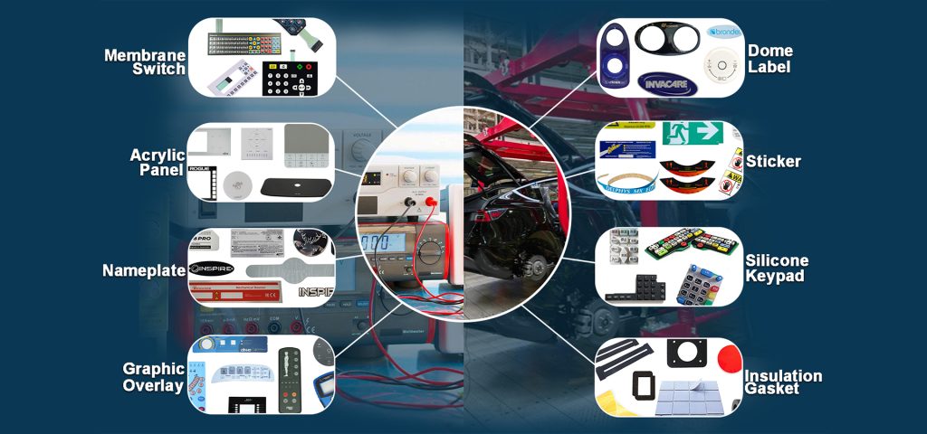
Bx-Panel has been at the forefront of the electronic printing and HMI industry for nearly 10 years. Located in Xiamen, Fujian, China, we operate a state-of-the-art 3,000㎡ manufacturing facility powered by over 100 skilled workers and a dedicated, innovative design team.
As a premier membrane switch manufacturer, our extensive business scope includes:
From prototyping to high-volume production, we ensure high yield, superior quality, and competitive pricing for clients globally.